Designing mmWave Phase Shifters: Concepts, Architectures, and Implementation
Part 1: Introduction to mmWave Phase Shifters – History, Metrics, and Architectures
Why Phase Shifters Matter
In the world of modern wireless and radar systems, phase shifters are indispensable. Their primary role is in scanning phased-array antennas, where the direction of a beam can be steered electronically without any mechanical motion.
This makes them crucial in:
- Military radar & tracking systems – early warning radars, missile defense, and space surveillance.
- Satellite communications – both GEO and LEO constellations that demand electronically steerable, lightweight antennas.
- Automotive radar & intelligent highway systems – collision avoidance, adaptive cruise control, and tolling.
- Emerging 6G wireless links – where multi-gigabit per second data rates require highly directional beamforming at D-band frequencies.
In fact, in some phased-array systems, the phase shifters account for up to 40% of the total antenna cost. They are also critical in instrumentation, metrology, amplifier linearization, and power combining, making them a true backbone technology for RF and mmWave applications.
What is a Phase Shifter?
At its simplest, a phase shifter changes the phase of an RF signal without significantly altering its amplitude.
If the input is: Vin(t) = Acos(ωt)
the output is: Vout(t) = Acos(ωt+ ϕ)
Here, ϕ is ω the electronically controlled phase shift.
By applying this principle across hundreds or thousands of antenna elements, beams can be steered in real time, enabling arrays to “look” in different directions without moving physically.
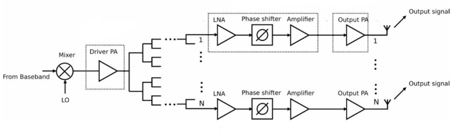
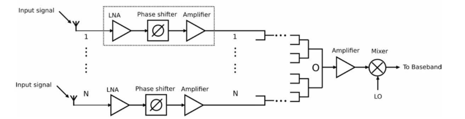
Phase shifters usually sit after LNAs in receivers and before PAs in transmitters, so their insertion loss, tuning accuracy, and switching speed directly affect the overall array performance — even down to bit error rate (BER) in digital communication systems.
A Brief Historical Context
Phase shifter technology has evolved in tandem with the needs of radar, space, and wireless communications:
Ferrite Phase Shifters (1950s–1970s)
- Dominated military radars and tracking systems.
- High power handling (kilowatt levels), but bulky and expensive.
Semiconductor Phase Shifters (1970s onward)
- GaAs MMICs, later SiGe, and InP.
- Compact, with lower power consumption and integrable.
- Enabled massive arrays like THAAD radar (60,000+ MMIC phase shifters).
Thin Film Ferroelectrics (1990s–2000s)
- Materials like BST enabled compact, tunable devices at microwave and mmWave frequencies.
MEMS Phase Shifters (2000s)
- Brought low insertion loss and good linearity at mmWave.
- Reliability and packaging remain challenges.
Superconducting Phase Shifters (experimental)
- Extremely low loss but requires cryogenic operation, limiting practical use.
This progression highlights a key theme: every generation of technology traded size, bandwidth, cost, and linearity, while the push towards mmWave integration continues.
Performance Metrics of Phase Shifters
Before diving into architecture, it’s essential to understand how phase shifters are evaluated. Designers weigh several performance metrics when selecting the right approach:
- Phase Range – Ideally 0°–360° for full steering coverage.
- Phase Resolution – Smallest incremental step or tuning smoothness, critical for precision.
- Bandwidth – Determines how consistent performance remains across frequency. Wideband designs are needed for multi-GHz links.
- Insertion Loss (IL) – Any power lost through the device; lower is always better.
- Return Loss (RL) – Matching quality; poor RL means reflections that degrade array efficiency.
- Linearity & Power Handling – Important for transmitter arrays; nonlinearities cause distortion.
- DC Power Consumption – Passive types consume little; active ones (like vector-sum) may draw more.
- Size / Integrability – Ferrite is bulky, but MMIC/SiGe solutions allow compact integration.
- Switching Speed – Determines how fast beams can be steered (ns for semiconductors, μs for MEMS/ferrite).
- Accuracy & Phase Error – Even small errors across many array elements can worsen sidelobe levels.
Types of Phase Shifters
Several architectures exist to implement phase shifting, each with strengths and limitations. Four of the most important are:
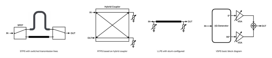
🔹 Switched-Type Phase Shifters (STPS)
- Principle: Use switches (SPDT) to toggle between paths of different electrical lengths or filters.
- Pros: Simple, digital, high linearity, good power handling.
- Cons: Bulky, high insertion loss, limited resolution unless cascaded.
- Use: Low-frequency phased arrays.
🔹 Reflective-Type Phase Shifters (RTPS)
- Principle: Signal is reflected off a tunable reactive load (e.g., varactor), and its phase changes.
- Pros: Continuous analog tuning, compact.
- Cons: Limited phase range (<180° per section), bandwidth depends on couplers, and gain imbalance.
- Use: Adaptive phased arrays needing fine analog control.
🔹 Loaded-Transmission Line Phase Shifters (LLPS)
- Principle: Transmission lines loaded with tunable reactances (e.g., varactors) change propagation constant → phase shift.
- Pros: Compact, can be digital or analog.
- Cons: Narrowband, limited phase range (<90°), poor return loss in extremes.
- Use: Compact IC designs where area is a premium.
🔹 Vector-Sum Phase Shifters (VSPS)
- Principle: Split into in-phase (I) and quadrature (Q), adjust amplitudes with VGAs, recombine.
- Pros: Wideband, 360° continuous tuning possible, small chip area.
- Cons: Active devices → higher power, lower linearity, practical tuning gaps.
- Use: mmWave phased arrays (6G, automotive radar).
Comparison of Phase Shifter Architectures
| Metric | Switched-Type (STPS) | Reflective-Type (RTPS) | Loaded-Transmission Line (LLPS) | Vector-Sum (VSPS) |
|---|---|---|---|---|
| Bandwidth | Narrow | Narrow | Narrow | Wide |
| Passive/Active | Passive | Passive | Passive | Active |
| Phase Control | Digital | Analog/Digital | Analog/Digital | Analog/Digital |
| Power Consumption | Low | Low | Low | High |
| Chip Area | Large | Large | Large | Small |
| Linearity | High | High | High | Limited |
| Output Power | High | High | High | Low–Medium |
| Insertion Loss | High | High | High | Low |
| Return Loss | Medium | High | Low | High |
References
- Kebe, M., Yagoub, M. C. E., & Amaya, R. E. (2025). A survey of phase shifters for microwave phased array systems. International Journal of Circuit Theory and Applications, 53(6), 3719-3739.
- Romanofsky, R. R. (2007). Array phase shifters: Theory and technology (No. E-16067).
- M. Najmussadat, R. Ahamed, M. Varonen, D. Parveg, M. Kantanen, and K. A. I. Halonen, "220-240-GHz High-Gain Phase Shifter Chain and Power Amplifier for Scalable Large Phased-Arrays," in IEEE Access, vol. 11, pp. 23565-23577, 2023, doi: 10.1109/ACCESS.2023.3253764. keywords: {Phase shifters;Gain;Receivers;Power amplifiers;Noise figure;Transmitters;Radio frequency;Differential coupler;gain tuning;low-noise amplifier;millimeter-wave;MMIC;phased-array;phase shifter;power amplifier;receiver;transmitter},
 Rupok Das, Engineer – I